Free Space Path Loss (FSPL)
Understanding how RF signals lose strength over distance, even in perfect conditions
Learning Objectives
By the end of this lesson, you will understand:
- What Free Space Path Loss is and why it occurs
- The FSPL formula and how frequency and distance affect loss
- Why higher frequencies suffer more path loss
- How antenna gain compensates for path loss in real-world systems
- Real-world applications in point-to-point wireless links
What is Free Space Path Loss?
An electromagnetic signal loses strength as it passes through obstacles like walls, floors, and furniture. That's easy to picture. What's less obvious is that a signal also loses strength even in empty space. This is called Free Space Path Loss (FSPL).
Think of a Flashlight
Imagine shining a flashlight in a dark room:
- Close to the flashlight: The light beam is small and bright
- Far from the flashlight: The same light covers a much larger area but is dimmer
- Same total energy: The flashlight hasn't gotten weaker - the energy is just spread out
- Your eye receives less: Each square inch receives less light because it's distributed over more area
RF waves work exactly the same way! The transmitter doesn't lose power, but the receiving antenna captures less of the total energy because it's spread over a larger spherical area.
The Spherical Spreading Effect
At Transmitter
All energy concentrated at source
1 km Distance
Energy spread over larger sphere
2 km Distance
Same energy, even larger sphere
The FSPL Formula
There is a formula to calculate FSPL. You are very unlikely to be asked to calculate this by hand in the exam, but you should recognize what it represents and how frequency and distance affect it:
Expanded:
Free Space Path Loss (dB) = 36.6 + 20 log₁₀(frequency in MHz) + 20 log₁₀(distance in km)
36.6
Physics Constant
Speed of light + spherical spreading (4π) + unit conversions
20 log₁₀(f)
Frequency Effect
Higher frequency = more loss
(f in MHz)
20 log₁₀(D)
Distance Effect
Greater distance = more loss
(D in km)
What Matters for Intuition
- Increase the distance → FSPL increases
- Increase the frequency → FSPL increases
- Useful rule of thumb: Doubling the distance adds about 6 dB of loss
Why Frequency Matters
Higher-frequency signals attenuate more than lower-frequency signals over the same distance. That's why, for example, a 5 GHz WiFi signal will suffer more free space loss than a 2.4 GHz signal over the same path.
2.4 GHz
Lower frequency component
5 GHz
6.4 dB more loss than 2.4 GHz
6 GHz
8.0 dB more loss than 2.4 GHz
WiFi Frequency Reality
This explains why you often see different behavior between WiFi bands:
- 2.4 GHz: Better range, penetrates walls better
- 5 GHz: Shorter range, more affected by obstacles
- 6 GHz: Shortest range, requires more access points for coverage
Design Impact: Higher frequency bands need more access points placed closer together to achieve the same coverage area. This is fundamental physics, not a limitation of the equipment!
Distance Effects & the 6 dB Rule
A useful rule of thumb is that doubling the distance adds about 6 dB of loss. Let's see why this works using the full FSPL formula:
Distance Doubling Examples
100m calculation:
FSPL = 36.6 + 20 log₁₀(5000) + 20 log₁₀(0.1)
FSPL = 36.6 + 74.0 + (-20) = 90.6 dB
200m calculation:
FSPL = 36.6 + 20 log₁₀(5000) + 20 log₁₀(0.2)
FSPL = 36.6 + 74.0 + (-14) = 96.6 dB
Difference: 6.0 dB more loss
500m calculation:
FSPL = 36.6 + 20 log₁₀(2400) + 20 log₁₀(0.5)
FSPL = 36.6 + 67.6 + (-6) = 98.2 dB
1000m calculation:
FSPL = 36.6 + 20 log₁₀(2400) + 20 log₁₀(1.0)
FSPL = 36.6 + 67.6 + 0 = 104.2 dB
Difference: 6.0 dB more loss
Signal Strength vs Distance (5 GHz Example)
Each distance doubling adds exactly 6 dB of path loss
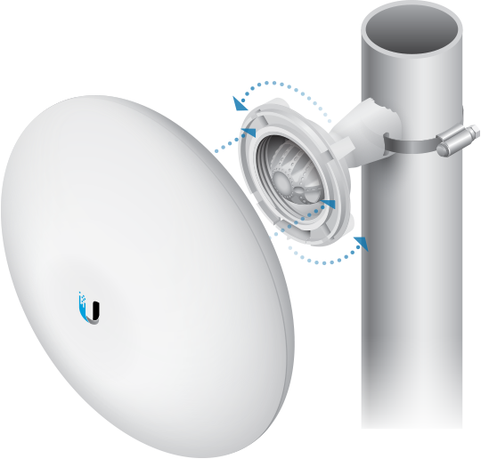
Real-World Example: NanoBeam Link
A good real-world example is Ubiquiti (UniFi) NanoBeam point-to-point radios. These typically operate around 5 GHz and, in clear line-of-sight conditions, can link sites many kilometres apart.
Example Calculation
Link Parameters:
- Frequency: 5000 MHz (5 GHz)
- Distance: 1 km
- Clear line-of-sight
Step-by-Step FSPL Calculation:
How Antenna Gain Fights Path Loss
NanoBeam antennas are highly directional, more like RF laser pointers than light bulbs. They typically have around 25 dBi of gain on each end.
Link Budget Analysis
❌ Losses
-110.6 dB
✅ Gains
+25 dBi
+25 dBi
+50 dB
Plenty of signal margin above receiver sensitivity!
Omnidirectional Antenna
Like a light bulb - spreads energy in all directions
Lower gain (2-8 dBi)
Directional Antenna (NanoBeam)
Like a laser pointer - focuses energy in one direction
High gain (20-30 dBi)
FSPL Calculator
Practice calculating FSPL for different frequencies and distances with this professional RF calculator:
Professional FSPL Calculator
Use this external calculator to practice FSPL calculations with automatic unit conversions and detailed explanations.
Open FSPL CalculatorTry the examples: 2.4GHz @ 100m, 5GHz @ 1km, 6GHz @ 50m
Quick Reference Values
≈ 80 dB
≈ 87 dB
≈ 107 dB
Why This Still Works in Real Networks
When designing point-to-point wireless links or other WiFi systems, FSPL is part of the link budget. It tells you how much signal will be lost just due to distance and frequency, before you even think about antennas, cables, or interference.
Real-World Applications
Point-to-Point Links
- Building-to-building connections
- Campus network backbone
- Remote site connectivity
- Wireless ISP infrastructure
WiFi Coverage Planning
- Access point spacing calculations
- Power level optimization
- Frequency band selection
- Coverage hole prediction
Knowledge Check
Test your understanding of Free Space Path Loss concepts.
Question 1: What happens to FSPL when you double the distance?
Question 2: Why does 5 GHz WiFi have shorter range than 2.4 GHz?
Question 3: What is the primary cause of Free Space Path Loss?
Continue Your CCNP Wireless Journey
Master RF propagation concepts step by step
1.2a Signal Strength
Learn about power measurements, dBm, RSSI, transmit power, and receive sensitivity in wireless systems.
Coming Soon1.2b Interference & Noise
Understanding RF interference sources, noise floor, rogue APs, and mitigation strategies.
Coming Soon1.2d SNR
Master Signal-to-Noise Ratio calculations and optimization for wireless performance.
Coming SoonCourse Progress
Professional WiFi Design & Implementation
Understanding FSPL is critical for enterprise wireless design. At Sprintwave, we apply these RF fundamentals to deliver high-performance wireless networks across Norfolk and beyond.
Enterprise WiFi Solutions
- Professional RF Site Surveys - Using industry-standard tools to map coverage and interference
- FSPL-Based Network Planning - Optimal access point placement using path loss calculations
- Multi-Frequency Design - Leveraging 2.4GHz, 5GHz, and WiFi 6E (6GHz) bands effectively
- Capacity Planning - Ensuring adequate performance for high-density environments
Point-to-Point Links
- Long-Distance Connectivity - Building-to-building links up to 30km+
- Link Budget Analysis - Professional FSPL calculations and fade margin planning
- Ubiquiti & Mikrotik Networks - Enterprise-grade point-to-point solutions
- Redundant Connections - High-availability wireless backbone links
Large Property WiFi
Country estates, manor houses, and multi-building sites requiring comprehensive wireless coverage
Industrial Networks
Harsh environment deployments with high-gain directional antennas and weatherproof equipment
Educational Sites
Schools and colleges requiring high-density WiFi with comprehensive coverage across multiple buildings
Planning a Wireless Network Project?
Get professional RF design services from certified wireless engineers. We apply CCNP-level expertise to every project, ensuring optimal performance and coverage.
Serving Norfolk, Suffolk, Cambridge & East Anglia